The Video Extensometer
Zwick VideoXtens
Introduction
When determining the mechanical properties of today's varied range of materials and samples it is essential to use accurate testing machines and instrumentation which do not influence any results obtained. Stress and strain are the two main parameters from which most mechanical properties are derived from uniaxial testing.Stress is normally calculated by measuring the initial specimen cross sectional area and relating this to the measured load obtained from a calibrated load cell whilst loading the specimen via grips or adapters. Care must always be taken to ensure the fixation method, alignment or specimen's shape does not influence the results obtained.
For rigid materials, strain can be measured by using conventional 'clip-on' mechanical extensometers or foil strain gauges bonded to the specimen. These devices however are not usually suitable when testing delicate materials such as fibres, films, foams or soft plastics as their weight and method of attachment can influence both the results obtained and the rupture point.
In many instances it is required to establish the material properties over large strain ranges up to rupture point. Most mechanical devices have limited travel and require removing from the specimen before fracture. Testing specimens under environmental conditions i.e. elevated temperature restricts the use of many mechanical units.
Various non-contacting systems such as mechanically driven optical followers and laser extensometers have been available over recent years, but these systems do not posses the necessary resolution for accurate determination of material properties at low strain levels, also these devices operate on a single measuring line between targets and hence require a second system if transverse strain is to be simultaneously measured.
In order to overcome these limitations the ME-46 Full Image Video Extensometer was developed by Messphysik GmbH, an Austrian company, based on the concept that "If it can be Seen, then it can be Measured."
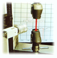
ME-46 Video Extensometer fitted on
Universal Testing Machine
Extensometer Equipment
The system comprises a Video Camera capable of allowing all in-built features such as gamma correction and filters to be easily adjusted in order to obtain the best image. The camera is fitted with a high precision CCD (Charge Coupled Device) chip having its many photo-sensitive elements arranged as an accurate linear grid.Interchangeable, high precision lenses are fitted to the camera, these can be fixed focal length units chosen to suit specific applications or 'zoom' lens which cover a far wider range of specimen sizes and deflections without having to adjust the camera location.
The camera is connected to a 'frame-grabber' interface card fitted in a PC running Windows 9x/2000/NT© based software.
The PAL video signal is converted into 8 Bit digital format whilst simultaneously generating a 640 x 480 pixel image on the monitor.
The interface card is capable of resolving 256 shades of grey for each pixel, resulting in a minimum resolution better that 1:131,073 (i.e. 17bit) of the camera's field of view. The actual working resolution is considerably enhanced by software interpolation techniques whilst simultaneously measuring the values of multiple scanned lines. The camera's field of view depends upon the focal length of the lens fitted and the distance away from the specimen.System inaccuracies are confined to lens defects, the linearity of the camera CCD chip and in maintaining a constant distance between camera and specimen during testing.
The video extensometer PC can be directly connected to the testing machine via either serial or IEEE interfaces, or alternatively by connecting an analogue load signal in order that load and strain data values are saved simultaneously. Facilities are provided to scale the analogue input signal so the monitor also provides a real time digital display of applied load.Control of the extensometer can be automatic from the testing machine computer or manual under Windows 9x/2000/NT© based software using the extensometer PC keyboard and mouse, thus allowing the system to
operate as a stand-alone unit with most makes of testing machines. When operating manually, the facilities are provided to set both the start and end test load values between which the test data is automatically saved in a tab delimited ASCII format.
Principle of Operation
The camera is rigidly fixed to the machine frame or tripod mounted and focused on contrasting targets marked on the specimen. It is imperative the distance between camera and specimen remains constant during testing as any movement will alter the image size which in turn will be erroneously interpreted by the software as a change in specimen size. Provided the testing machine frame is of adequate stiffness and the specimen grips accurately aligned then this problem should not occur. The specimen should also be illuminated at a constant level during testing and this is best achieved using a separate external source.
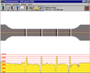
Monitor display showing axial targets
and Grey Scale histogram
Targets are marked by producing straight lines on the specimen using paint, a felt marker pen of a contrasting colour or by attaching self adhesive targets, alternatively the specimen outline can be used for specimen width targets and also for axial deformations with ridged specimens. It is essential the targets create a sharp and as great a contrast difference as possible to ensure correct automatic target recognition and tracking. The target position is detected at the edge of a contrast transition and is hence not affected by changes in target
width.Conventional extensometers must be attached to specimens at a known gauge length and the extension signal obtained is converted into a strain value. This method can result errors as normally it is not possible to verify the exact gauge length once the extensometer is fitted on the specimen. The video extensometer operates as a 'strain meter' by directly calculating the measured extension as a percentage of the original length and only requires exact knowledge of the initial gauge length if actual extension values are required. A calibration facility for axial and transverse axes is provided to enable actual distances between targets to be displayed and saved.
The camera viewed image is usually rotated through 90° when displayed on the monitor as specimens are normally tested in a vertical mode and this allows the screen aspect ratio to be used to the best effect.
The viewed image is digitised and the resulting grey scale values (0..255) for each pixel stored in a continuously refreshed Frame Buffer memory location. From this information it is possible to produce a grey scale (contrast) diagram for every horizontal scan line or vertically at any horizontal pixel position.Due to the large amount of data obtained from each picture scan, it is essential this is efficiently processed in order that the extensometer has a dynamic capability suitable for use with conventional static testing machines. Using the Frame Buffer information the software automatically detects the gauge marks and follows them during testing.
Facilities are provided in the configuration set-up menu to select the target edge colour e.g. black to white, white to black, black or white object outer edges and with these combinations it is possible to accommodate most specimen types.
Targets are automatically detected by differentiating the grey scale data along the scan axis to ascertain the rate of change in values and then selecting the maximum values as the targets.
The software automatically detects the number of peaks corresponding to the number of marks known to have been fitted and selects these as the targets.
Reference marks are shown on the video monitor indicating the selected targets found within manually selected window and the operator is given the opportunity to manually select alternatives in the event they have been incorrectly detected.
In order to assist the operator in setting the camera aperture to obtain the correct target identification, provision is made to display the grey scale level of the datum scan line as a histogram on the video monitor.Having established the differential signature pattern, memory zones are defined around each target values in the Frame Buffer so that only data within these locations is further processed.
The target datum points for a scan line are selected at the mean grey scale level of the maximum and minimum values of the selected gradients as shown below.
In order to enhance the accuracy and resolution of measurement, the mean grey scale point is carried out over an operator selected band of scan lines either side of the datum and the mean length computed from these values.
The crossover points are dynamically adapted throughout the testing processso that targets are not lost if the target edge contrast reduces due to the specimen stretching. This method of measurement makes it possible to obtain resolutions far better than the theoretical minimum value of 1:131,073 of the field of view.For the study of axial strain distribution, up to 10 targets can be fitted, and the measuring process is automatically carried for each zone with the individual lengths being saved.
Using the same technique as previously described, the image can be scanned at right angles to the specimen axis and the data obtained used to measure width. The specimen width outline can be used as the width target or alternatively marks can be placed on the surface. The width can be measured at multiple equispaced distances between the outer axial targets with the individual values being saved, thus allowing the study of transverse strain distribution. A 'Neck-tracking' facility can be selected, whereby the specimen width is continuously scanned and the minimum value detected and measured through to rupture.All length and width values are transmitted to the machine controlling PC or stored to disk in tab?delimited format together with details of the elapsed test time and load values, making it easy for post test processing using Messphysik software or conventional spreadsheets.
After the above processes have taken place the frame information is refreshed and the exercise repeated. The time between refresh cycles depends not only upon the speed of the computer and frame grabber card but alsoupon the amount of data being processed. In practice using the standard Messphysik extensometer to just measure axial deformation over a 10 scan line band the refresh frequency is in the order of 100Hz, however if width is also simultaneously measured and averaged at 3 positions the refresh frequency falls to approximately
30Hz.
Method of Operation
Windows© based software is used to control all extensometer operations and procedures.Firstly, the specimen is marked and then placed in the testing machine. The camera which is ideally attached to the machine frame is positioned and adjusted so that the video image clearly shows the targets and has a sufficient field of view to display them throughout the test.
The position of the axial datum is set using the mouse and the histogram displays the grey scale values along this scan line scan line, allowing the lens iris and external lighting to be adjusted for the correct contrast condition.
The extensometer can be calibrated by placing a known distance piece adjacent to the specimen face or measuring the specimen width/diameter with a micrometer. These targets points are then selected using the computer mouse and their known values entered, this results in a recalculation and display of the size of the monitor's field of view. Provided the camera is not moved or the lens adjusted between tests, subsequent specimens will be automatically measured without recalibration.
If transverse strain is required for the calculation of true stress, n value, Poisson's ratio etc. the operator selects the number of zones between the axial targets over which it is to be measured and whether the mean or minimum value is to be recorded. When the minimum value is selected the system automatically searches and tracks the neck value.
The specimen image is continuously displayed on the monitor during a test together with lines indicating the axial and transverse points being measured.
Several calculated values can also be displayed in real time having been selected by the operator from a configuration menu. These can be axial and transverse values, Poisson's ratio, r-value, operating frequency etc.All extensometer and target settings are held in a named parameter file which can be easily recalled when testing similar specimens at a future date.
When starting a test, the software automatically identifies the targets and indicates these on the monitor. The operator confirms the targets have been correctly identified, or alternatively points to the correct ones using the mouse.All targets are automatically tracked during testing with the measured values being transmitted to the testing machine control computer, or when configured as a stand alone unit, the data is saved to disk in a tab delimited format with a unique file name. The following data is saved: elapsed time, load and crosshead/piston displacement (obtained from an A/D card connected to testing machine), axial extension and transverse extension.
The stored data can be evaluated using Messphysik or conventional spreadsheet and statistical software packages.Application Examples
The following stress/strain diagrams illustrate the suitability of the ME46 extensometer for testing elastic and high strength metals.Some plastics standards specify the material modulus must be calculated between low fixed strain values (i.e. 0.05 to 0.25%) and that extensometer resolution must be better than 1mm irrespective of gauge length or measuring stroke. It is also usually necessary to test and record strain to rupture, which for plastics can be in the order of 800%, consequently on a specimen with a 50mm gauge length the extensometer would require a resolution better than 1/400,000,000 to meet the standard. Although the extensometer provides adequate data for accurate modulus calculation it is recommended that comparative checks for modulus values are carried out with the field of view set to cover the prescribed strain range to comply with the standard.
Optional Configurations
The system can be fitted with a Digital/Analogue interface to provide simultaneous analogue outputs of both axial and transverse strain values and these signals can be used for closed loop control of servo machines.
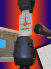
Video extensometer set up for 'dot measuring'
for strain distribution measurement over
a flat surface.
Accuracy
Current standards for classifying most extensometers used in metals testing (EN 100024, ASTM E83 etc.) have been formulated upon conventional devices which have fixed gauge lengths and as a result all values for accuracy, resolution have been based around percentages of the gauge length or operating range.The ME46 Videoextensometer has neither a fixed gauge length nor operating range as it depends upon where specimen targets are located and the selected field of view.
Axial Field of View Minimum Resolution 50 mm < 0.4 µm 250 mm < 2 µm 500 mm < 4 µm 1000 mm < 8 µm
The minimum extension resolution which can be obtained due to number of pixels and shades of grey based upon a single scan line is related to the field of view and examples are indicated in the adjacent table. These values are greatly improved when utilising several scan lines and interpolation techniques.The software provides a real time digital display of the extension value to a resolution of 0.0001mm and it is this value which must be recorded when carrying out comparisons with established standards.
System linearity and errors can be checked using a calibration rig with the camera set for a standardised field of view based upon approximately 150% of the initial target length plus extension range to be calibrated. As can be seen from the graph below, the results obtained are excellent when compared with national standards.
Post Test Evaluation Software
A complete range software packages based upon National Testing Standards (EN 10002-2, ISO 527, DIN 53815 etc.) are available.
These packages can be run concurrently using a second PC allowing real time graphing whilst the test is in progress with the operator able to pre select the displayed axis and also allow automatic calculation of an extensive range of results in addition to producing individually configured test reports.
If the extensometer is used as a stand-alone extensometer then the data can be processed in a similar manner using the same software after a test has been completed.Because of its high resolution and simple operation the ME 46 Extensometer can be used over a very wide range of testing with the following data processing software options based upon National Test Standards.
Modulus, Proof Stress, Max. Load, Poisson's Ratio, r value,
strain at break, and many more values to be automatically
calculated.
Max. Load, Poisson's Ratio, energy under curve, strain at
break, and many more values to be automatically calculated.
accordance with DIN 53815
and radius of curvature can be calculated from the
deflections obtained.Software packages are continuously being developed to meet additional testing requirements.
Advantages of ME46 Videoextensometer
Non-contacting and therefore does not influence rupture point.
Although the system has been described for use with conventional tensile, compressive or bending tests, it can be used to accurately determine the movement of any object. i.e. movement of a bridge under load relative to ground, sideways movement of a wall relative a fixed reference line, extension of nerves, muscles or bones during surgical operations etc.
This article was created many years ago...
For more up-to-date information, download the following:
Extensometers >>
For the latest in Extensometers and Video Extensometers and other Materials Testing equipment, vist the Zwick Roell website : www.zwick.co.uk
For details of Sensor Suppliers, click here...
Home - Website - Search - Suppliers - Links - New Products - Catalogues - Magazines
Problem Page - Applications - How they work - Tech Tips - Training - Events -